Driving Bipolar Stepper Motors By Pic 16f84 Projects
- A Uni-polar stepper motor can be used as uni-polar or a bipolar stepper motor. Bipolar stepper Motor-A bipolar stepper motor can only be used as a bipolar. Bipolar Stepper Basics. A bipolar stepper motor has one winding per stator phase. A two phase bipolar stepper motor will have 4 leads.
- In BIPOLAR stepper motor we have phase ends and no center taps and so we will have only four terminals. The driving of this type of stepper motor is different and complex and also the driving circuit cannot be easily designed without a microcontroller. Articles and DIY projects from Circuit Digest.

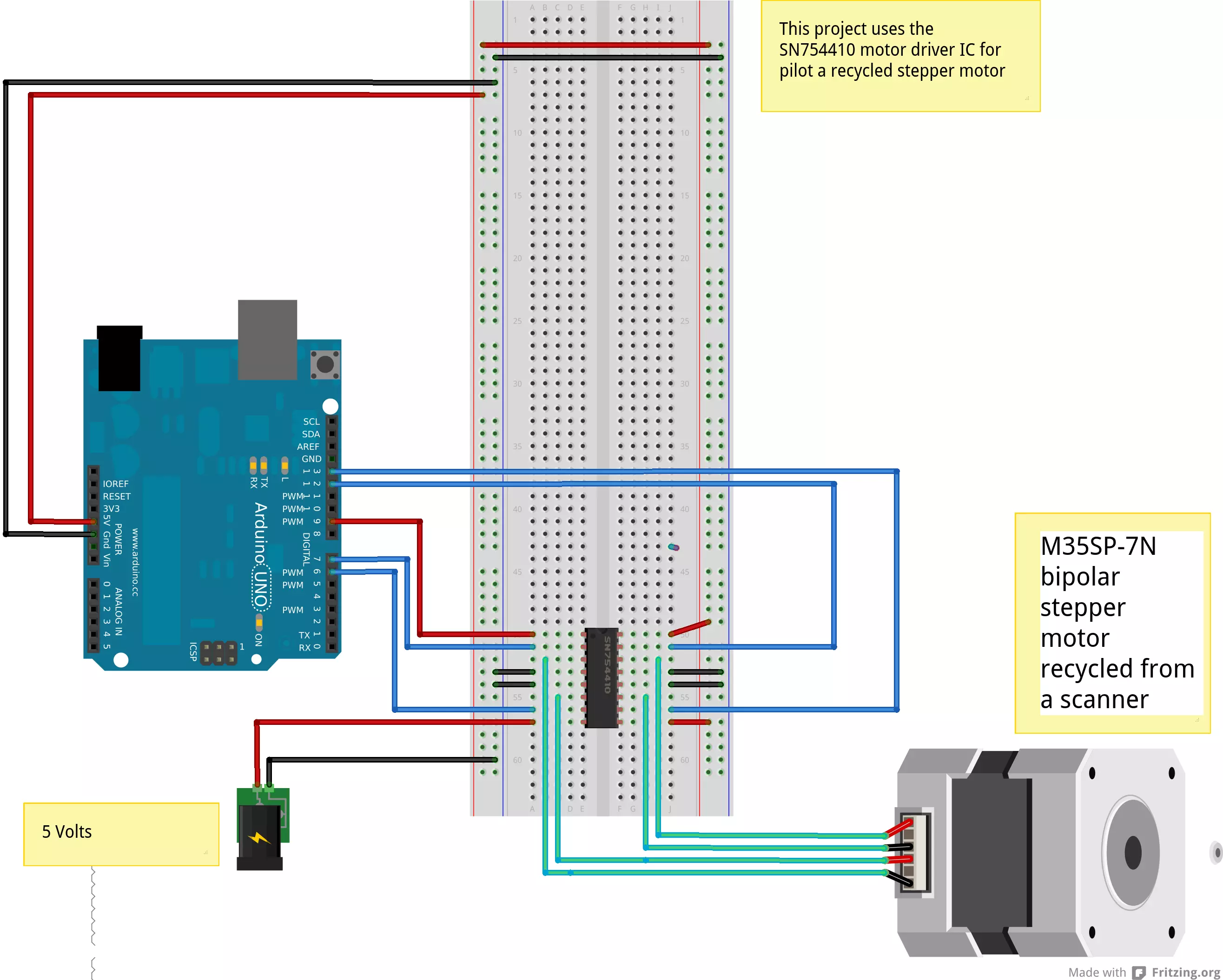
Driving a Bipolar Stepper Motor with Arduino and ULN2803AG – tutorial where is explained how a bipolar stepper motor can be controlled using eight identical Darlington inverting amplifier circuits and an Arduino board.
In previous blogs we learned the basics of stepper motors and how they function. Also discussed was the many uses at which stepper motors can be used. The next step in these articles is to take a bit more in depth look at the two different types of two-phase stepper motors. There are two basic winding arrangements for the electromagnetic coils in a two phase stepper motor, one being bipolar and the other unipolar.
Unipolar Stepper Motors
The unipolar stepper motor operates with one winding with a center tap per phase. Each section of the winding is switched on for each direction of the magnetic field. Each winding is made relatively simple with the commutation circuit, this is done since the arrangement has a magnetic pole which can be reversed without switching the direction of the current.

In most cases, given a phase, the common center tap for each winding is the following; three leads per phase and six leads for a regular two phase stepper motor. You will usually see that both these phases are often joined internally, this makes the stepper motor only have five leads. Often a stepper motor controller will be used to activate the drive transistors in the proper order. Since it is quite easy to operate these stepper motors, they are often very popular among hobbyists and are usually the cheapest way to get precise angular movements.
Bipolar Stepper Motors
With bipolar stepper motors there is only a single winding per phase. The driving circuit needs to be more complicated to reverse the magnetic pole, this is done to reverse the current in the winding. This is done with a H-bridge arrangement, however there are several driver chips that can be purchased to make this a more simple task.
Unlike the unipolar stepper motor, the bipolar stepper motor has two leads per phase, neither of which are common. Static friction effects do happen with a H-bridge with certain drive topologies, however this can be reduced with dithering the stepper motor signal at a higher frequency.
This is a brief introduction on how a stepper motor may vary between unipolar and bipolar.
Bipolar stepper motors can be a bit more difficult to operate, and the unipolar motor does feature twice the amount of wire in the same space. Different projects will require different types and settings of stepper motors. Browse the large selection to find the perfect one for your needs.
STEPPER MOTOR USING PIC MICROCONTROLLER,In this tutorial, you will learn to interface a stepper motor with PIC16F877A microcontroller. A stepper motor is a kind of a motor that converts electrical pulses into mechanical movement. Unlike all conventional motors, a stepper motor advances in steps. These steps of the motor are measured in degrees and can vary as per its application. It takes one step at the time and the size of each step is equal to the other.
Bipolar Stepper Motor Tutorial
There are three excitation modes of a stepper motor;wave drive, full driveand half drive. In wave drive mode, only one winding is energized at a given time, whereas in full drive mode, two phases are energized at the same time. The number of steps, however, are same in both wave and full drive modes. Half drive mode combines both wave drive and full drive i.e. it energizes one and two phase alternatively. TASK
To drive a stepper motor using PIC microcontroller
CIRCUIT DIAGRAM FOR STEPPER MOTOR USING PIC microcontroller :
Circuit diagram of stepper motor interfacing with pic16f877a microcontroller is given below:
Bipolar Stepper Motor Wiring
The easiest way of interfacing a stepper motor with a microcontroller is via ULN2003 transistor array chip. This IC has seven Darlington transistor drivers and is used for high current torque motors. In the circuit diagram, the four input pins (1B, 2B, 3B, 4B) of ULN2003 are connected to the lower significant bits of PORTD of the microcontroller and the output pins (1C, 2C, 3C, 4C) are connected to the ‘live’ pins of the stepper motor as shown above.

The ‘common’ pins of the stepper motor, together with ‘COM’ pin of ULN2003 are hooked up to a 12V battery supply.
Stepper motor speed
The speed of the stepper motor can be increased or decreased via Proteus as well. For this purpose, right click on the stepper motor and select ‘Edit Properties. The window on the right will appear on the screen.
Bipolar Stepper Driver Circuit
For a 200 step motor, a complete rotation (360°) is divided into 200 steps. This gives the size of a single step which is equal to 1.8°. You can vary the number ofsteps as well as the step angle using Proteus, the effects of which will be visible during simulation.
C-CODE FOR STEPPER MOTOR INTERFACING WITH PIC MICROCONTROLLER
Write the following code in the mikroC code editor window:
- void main()
- {
- TRISD = 0b0000000; // PORT D as output port
- PORTD = 0b1111111;
- do
- {
- PORTD = 0b00000011; // energizing two phases at a time
- Delay_ms(500); // delay of 0.5s
- PORTD = 0b00000110;
- Delay_ms(500);
- PORTD = 0b00001100;
- Delay_ms(500);
- PORTD = 0b00001001;
- Delay_ms(500);
- }while(1); // loop executed infinite times
- }
Bipolar Stepper Motor Controller Circuit
The above code represents the working of a stepper motor in full drive mode. For wave drive and half drive modes, slight changes will be required in the above code. The circuit diagram, however, remains the same. The PORTD of the controller has been declared as an output port which is fed to the driver IC ULN2003. The combination of bits from PORTD of the controller is transferred to the input pins of the IC, which enables it to switch the different coils of the motor on and off.
Bipolar Stepper Motor Driver Circuit
APPLICATIONS :
Stepper motors are used immensely in our daily life. They are used in automobiles, digital photocopiers, computer printers, to move the print head carriage, and other home appliances. Stepper motors are also used in industrial machines, security and medical equipments.
Bipolar Stepper Motor Arduino
To dowload circuit diagram and code of stepper motor control using pic microcontroller click on following link :
you can help us and others by sharing this article with your friends. Thanks 🙂